
Bad grounds, voltage drops, ground offsets, open circuits, dirty power and electrical noise are all terms that you are likely to come across when dealing with automotive electrical systems. Today’s production vehicles have more electrical connections and wiring than ever before. Even full race cars are challenged by more wiring and connections to accommodate an ever growing list of “essential” sensors to deliver data. To compound this issue, the number of low-current circuits which are more sensitive to issues has also increased. To avoid and remedy these issues, a thorough understanding of the causes, symptoms, diagnostics and treatments are a must.
By Michael Ferrara and Scott Borg // Photos by Joe Singleton
DSPORT Issue #189

Gremlins Attack Everyone
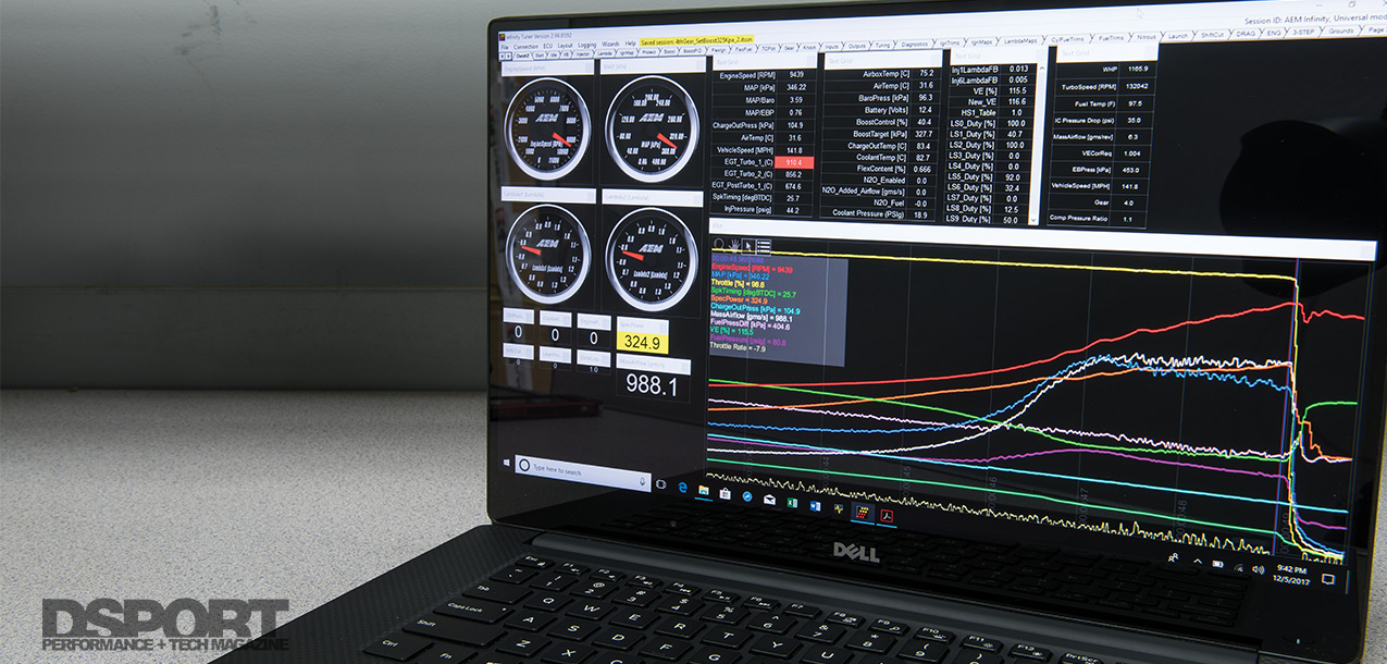
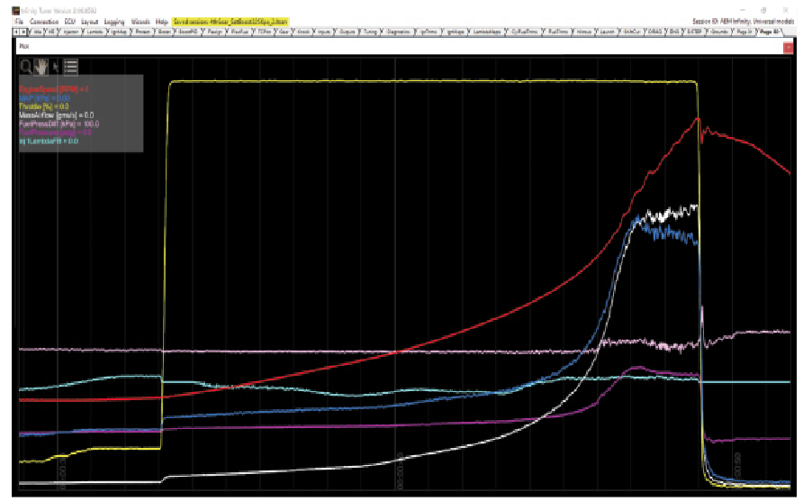
As the son of an electrician that spent a dozen summers sweating my ass off jerking wires in hundreds of houses in South Florida, I’m no stranger to basic electrical theory. Add in the fact that I hold an Engineering degree in Mechanical and Aerospace Engineering and you might think there isn’t an electrical issue that could stump me. Nothing could be further from the truth. Despite my practical experience and academic training, I too get stumped. Most recently, a thorough inspection of logs from our Project RH8 R33 GT-R showed signs that a Gremlin was at work. TPS, MAP and Lambda signals were all being affected causing the Lambda feedback to turn off after 7000RPM. Only after a dozen hours was the Gremlin found and exorcised from the vehicle. The result was we now have sensors that are working correctly allowing the ECU to work properly.
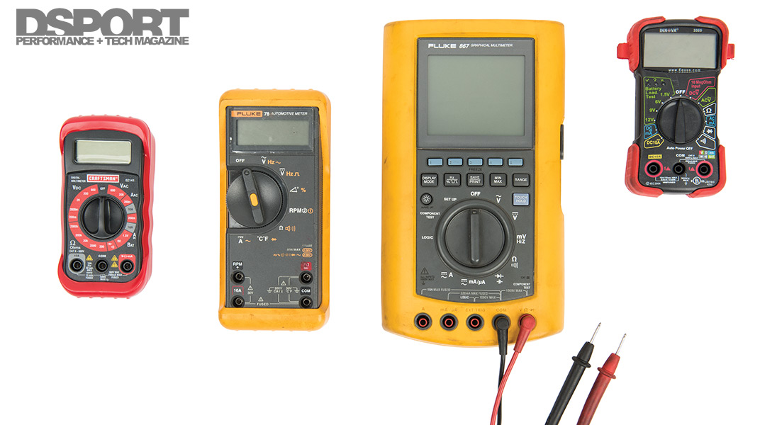
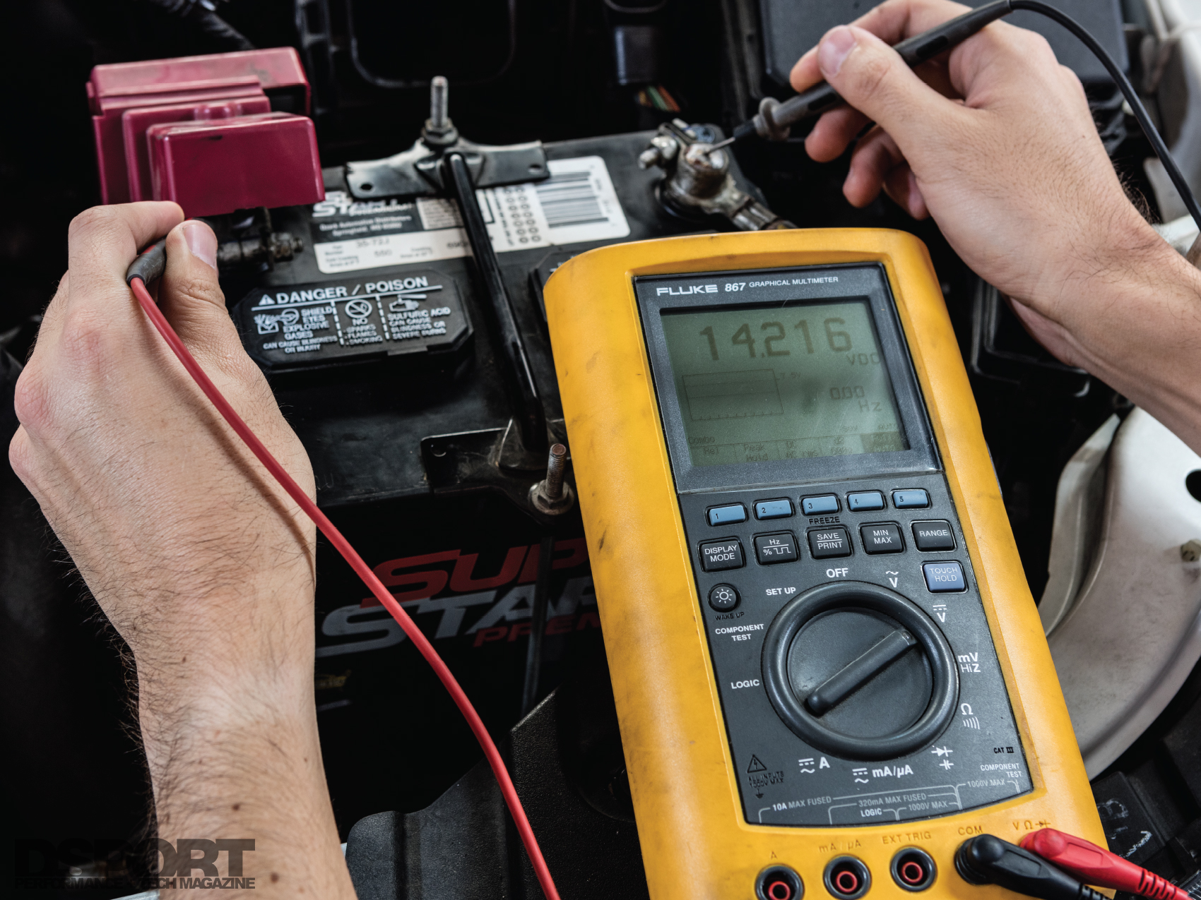
A high-quality Digital Multi Meter (DMM) is a must for automotive electric troubleshooting. Make sure the unit has high-impedence inputs and that the display goes to at lease 3 decimal places.
Basics: The Circuit, Power & Ground
In the most basic direct-current (DC) electrical circuit, you will find a power source (battery) with positive (+) and negative (-) terminals, some type of DC electrical device (light, motor, heater, etc.) and wires. The most basic “Safe” circuit will also include a current limiting safety device (fuse or breaker). When a wire is making contact from the positive post of the battery to the positive input of the device AND when a wire is making contact from the negative post on the battery to the negative input on the device, the circuit is said to be closed. When a circuit is closed, the electrons are able to race around and power the device. If either wire is disconnected or suffers a break of some sort, the circuit is said to be open and the device will cease to function until the circuit is closed again.
Issue #1: Open Circuit
One of the simplest and most common electrical issues on an automobile is an open circuit. As mentioned earlier, the circuit can become open on either the power or ground side of the circuit. On the power side, a blown fuse is most likely the cause of the open circuit (finding out why the fuse blew is extremely important, but more on that later). Loose or corroded terminals at the battery or a broken wire on the power side are also possible causes.
On the ground side of the circuit, the most likely culprit is the location where the ground wire makes contact with the chassis or battery. If you ever experience a vehicle that sometimes has no power when you go to crank the engine, check the negative terminal at the battery first. If it’s loose or corroded, it can cause all types of intermittent issues. While loose or corroded terminals and broken wires in the branch circuits can also be a possibility, it’s most often the location where the negative battery lead meets the chassis that causes the issue.

Attacking Issue #1: Open Circuits (Device won’t turn on)
1.Check the battery terminals. Make sure that there is a clean, tight and corrosion-free connection.
2.Use a digital multimeter (DMM) to check the continuity across all of the fuses. This is a better method than a simple visual inspection. Replace fuses that have failed with the same rating fuse. Try to determine why the fuse blew in the first place.
3.Check the terminals at the actual device for corrosion or looseness. If the device starts to work as the wires are wiggled, a new connector may be all that is needed.
4.Follow the leads to any chassis grounding point. Check for looseness or corrosion.
5.Back probe the device with the connector attached and see if there is voltage at the component. If there is proper voltage at the connector when attached, go to step 6. If there is no voltage at the connector or only voltage with the connector disconnected, there may be an issue in the circuit that will require a voltage offset probe session to locate the issue.
6. Remove the device from vehicle and apply 12V to see if it works on the bench.
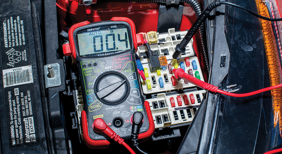
Fuses are one of the easiest items to check when a circuit goes out. Instead of just making a visual inspection, using the DMM to test continuity across the fuse posts will be more accurate and quicker.
Know Your Grounds (Chassis vs. Sensor)
All modern vehicles are set up with two types of grounds: chassis and sensor. The chassis ground systems attaches the negative post of the battery to the chassis of the vehicle. From this point, there is usually additional ground wires connecting the engine, transmission and body to this chassis ground. One reason that the OEMs run a chassis ground strategy is to eliminate the need to have every component run a dedicated ground wire back to the battery. Instead, the chassis ground can be picked up from just about any metallic point on the body, chassis or engine. Unfortunately, there is a trade off in not having the ground for every electrical component run directly to the battery. Whenever there is resistance between one of the grounding points on the chassis and the battery, a voltage drop will be present. Hence, a grounding loop is created. Grounding loops are not desirable as they cause small currents to be conducted due to the voltage offset and they can also produce noise. While most of the high-current devices are not affected by the noise, the ultra-sensitive low current devices (such as sensors) can be affected even if they are tied into a dedicated sensor ground.
Sensor grounds are the series of grounds that are independent of the chassis grounds and tie into the ECU’s sensors and the ECU. This is a specialized low-current circuit that will cause nightmares when a grounding issue occurs. If a ground loop is present in the sensor grounds, even small voltage offsets can cause big errors in sensor outputs causing the vehicle to run poorly.
Issue #2: Ground Issue (Chassis Grounds Only)
A “bad” ground can cause a completely open circuit as described above or it may just cause a significant voltage drop. Since vehicles get worked on and items are sometimes overlooked, it is common to find some of the chassis grounds loose, corroded or simply never reattached. A poor chassis ground can cause the item relying upon this ground to have low or no output, or sometimes intermittent operation. While everyone seems to understand that the positive supply voltage side of an electrical circuit, many forget that any circuit is only as good as the quality of its ground. Checking the ground on any electrical circuit should be one of the first steps before considering the replacement of any electrical device.
Probing a connector from the front is called “front probing.” Since this method requires removal of the connector from the device, it will open the circuit and let no current flow. Hence, it is not recommended when trying to troubleshoot a circuit.

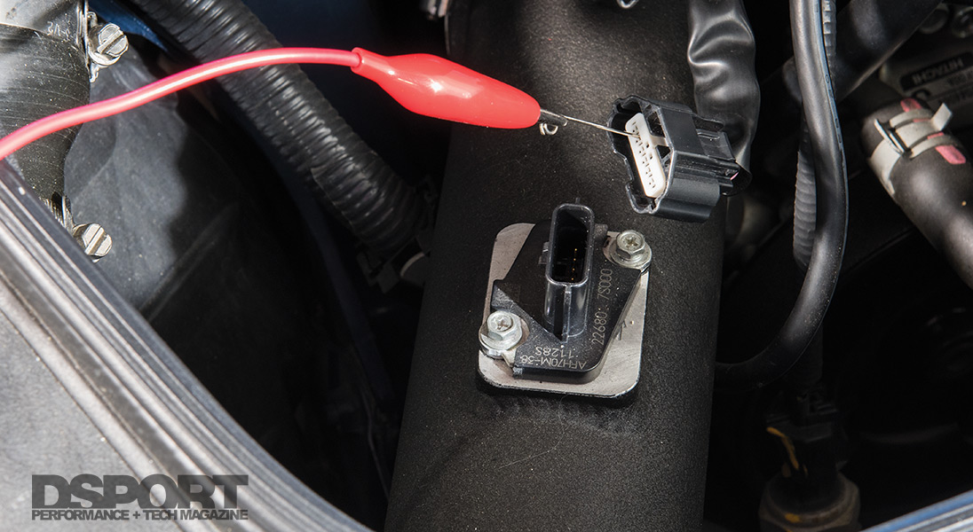
“Back probing” a connector while it is still attached to the device is the preferred method as current is flowing in the circuit. This makes it possible to take voltage offset or voltage drop measurements. Here the back probe is achieved with the help of a paper clip or pin.

A piercing probe makes back probing a much easier affair. These probes make a small hole in the insulation to touch the conductor. The hole is so small that it self heals in most cases when the probe is removed.
Attacking Issue #2: Chassis Ground Issues
1.Check the battery terminals. Make sure that there is a clean, tight and corrosion-free connection.
2.Follow the battery negative cable to its primary connection to the chassis. Ifthere are any signs of corrosion, detach, clean and re-attach. Replace cable if signs of corrosion under the insulator.
3.Perform a high-current chassis ground test (Starter/Engine):
a.Disable the fuel system by removing the fuel pump fuse and disconnecting the injectors so that they do not operate when the engine is cranking.
b.Set the DMM into the DC voltage mode. Connect one of the terminals to the battery negative post and the other to a grounding point on the firewall.
c.Turn on all high load electrical devices such as blower motor, headlights, rear electric defroster and record any voltage drops noted on the DMM.
d.Either use a remote starter or have a friend crank the engine for up to 10 seconds while you look at the DMM to see the voltage recorded.
e.The less voltage drop seen on the meter, the better. Readings of 0.2 volts or less are OK if the battery is rear mounted on the vehicle. If the battery is mounted in the front, the voltage drop should be in the 0.1 volt or less neighborhood. If the reading is higher, try cleaning the negative battery post and the connection point to the chassis and retry the test.
f.If results are not within spec, replace negative battery cable and retest. About 70 percent of the time, this will cure the issue. If not, continue to step 4.
4.Perform a high-current chassis ground test (All Loads/Chassis):
a.Disable the fuel system by removing the fuel pump fuse and disconnecting the injectors so that they do not operate when the engine is cranking.
b.Set the DMM into the DC voltage mode. Connect one of the terminals to the battery negative post and the other to a grounding point on the engine.
c.Either use a remote starter or have a friend crank the engine for up to 10 seconds while you look at the DMM to see the voltage recorded.
d.The less voltage drop seen on the meter, the better. Readings of 0.2 volts or less are OK if the battery is rear mounted on the vehicle. If the battery is mounted in the front, the voltage drop should be in the 0.1 volt or less neighborhood. If the reading is higher, try cleaning the negative battery post and the connection point to the chassis and retry the test.
e.If results are not within spec, replace negative battery cable and retest. About 70 percent of the time, this will cure the issue. If not, continue to step 5.
5.Follow the leads to any chassis grounding point. Check for looseness or corrosion. Clean off corrosion, clean terminal and connection point and reattach. Replace if a large voltage drop is present. Be sure that there is a load on the circuit when testing for the voltage drop (i.e. have the headlights on if checking the ground to the headlights).
6.Consider installing a “grounding kit” to improve the quality of the chassis ground throughout the vehicle. The grounding kit will use large gauge wire to carry the ground circuit from the battery to key locations that pick up the engine and chassis grounds used by the OEM. On some older vehicles, we’ve actually witnessed horsepower gains at the wheels as some older vehicles do not do a great job of isolating low-current sensors from the chassis ground (by using a dedicated sensor ground).
Issue #3A: Ground Issue (Signal Ground)
The signal ground circuit depends on an ultra-low resistance path that will show no voltage offset at the ground signal to each of the components (usually sensors) in the system. Because everything in these systems operates at such low currents, even a slight amount of added resistance (from a poor crimp or splice) can wreak havoc.
By definition the signal ground circuit should be independent from the chassis ground circuit on the vehicle. The only location where the two should ever make contact is inside the ECU. That means that if the ECU is unplugged from its harness, there should be no continuity between any signal ground and the chassis ground. If you own a late 80s to early 90s vehicle (or if anyone touched the wiring on any vehicle), there may be some exceptions to the rule. In these years, the OEMs had some different ideas about what sensors should be tied into signal grounds and what should be tied into chassis grounds. If you find continuity between the sensor ground and chassis ground pins on your ECU harness, you should be concerned.
Since a number of sensors usually share the same sensor ground and +5V supply, bad splices, poor crimps or even one bad sensor can cause issues on the entire sensor ground circuit.
Attacking Issue #3B: Signal Ground Issues
1.Disconnect the harness from the ECU. Identify the sensor ground pins as there are usually one to four pins.
2.With the DMM set to continuity or Ohms (resistance), connect one lead to the (-) at the battery and use the other lead to probe all of the sensor ground pins at the harness.
3.If there is no continuity, skip ahead to Step 8.
4.If there is continuity, begin disconnecting sensors until the continuity breaks.
5.If the continuity remains with all of the sensors disconnected, the issue lies in the wiring harness. This is the worst case which will require a trace of every wire in the harness.
6.If you had continuity but it was broken when a sensor was disconnected, make sure to reconnect any of the sensors that do not cause the continuity.
7.Remove the problematic sensors from the vehicle and see if the body of the sensor is making continuity with the signal ground pin on the sensor. If the sensor or device has both a sensor and chassis ground, check to see if there is continuity between these two pins. A new sensor or a different sensor (Bosch instead of Nissan knock sensor) may be needed. See Nissan Knock-Knock Sidebar.
8.Review the logs from the ECU to determine which sensors or devices are being affected and when (cranking only, all times, high engine loads only, etc.).
Issue #4: Voltage Drop Tests
To really evaluate the health of an electrical circuit, a voltage drop test should be performed. Since voltage will only be flowing through a circuit when it is “on” (closed), this test cannot be performed when a device is switched off or if you have an open circuit issue.
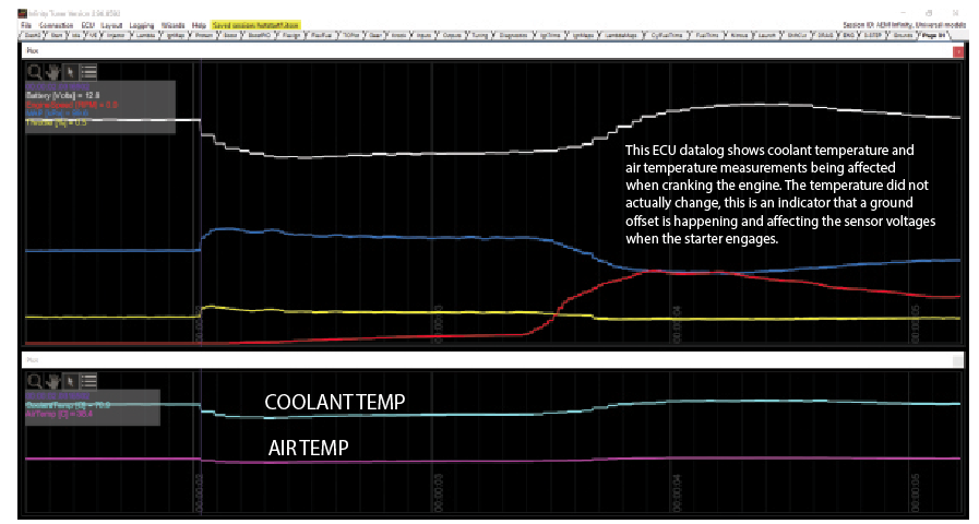
When there is an excessive voltage drop in the circuit, the issues can be many. Some electrical components will fail to operate. Other electrical devices may slow at high electrical loads. The engine may be hard to start or it may have erratic performance. You may even see high sensor voltages on certain sensors. Learning to measure the voltage drop at the multiple points in the same circuit will lead you to find the exact cause sooner without being led down a path that has you replacing multiple items.
A casual visual inspection of a circuit isn’t going to find a voltage drop. Probing a circuit across its connectors, switches, wiring and ground can isolate the problem area and make the repair much quicker.
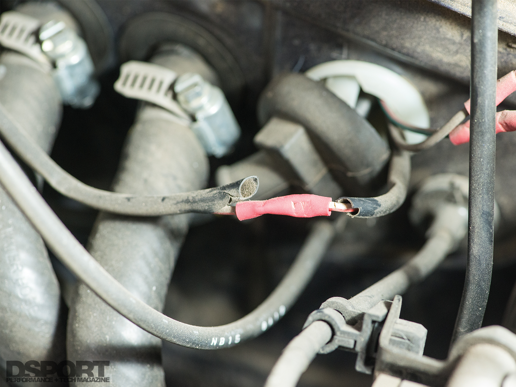
Voltage drops occur in a DC circuit due to excessive resistance. This excessive resistance can be the result of an improperly executed crimp, corrosion, a damaged wire, a dirty contact or a faulty device.

Before a voltage follower was installed to isolate the TPS signal sent to the factory ATTESSA-PRO AWD computer, the current draw caused all of the sensors sharing the same sensor ground pin to have skewed and erratic readings.
Attacking Issue #4: Voltage Drop Tests
1.Only circuits in operation can be tested, so make sure the switch is on if so equipped for the circuit.
2.Probing for a voltage drop can be done across a switch, connector, wire or ground connection. In lieu of a factory specification cited in a manual, use the following guidelines on standard and high-current circuits:
a.0.00V measurable voltage drop across any connections.
b.Less than 0.10V voltage drop between circuit ground and battery (-) post.
c.Less than 0.20V voltage drop on any length of wire.
d.Less than 0.30V voltage drop across any switches or relays.
3.Probing for a voltage drop on low-current circuits (ECU sensors) should meet the following standards:
a.0.00V measurable voltage drop across any connections.
b. Less than 0.10V voltage drop between sensor ground and sensor ground pin.
The Bottom Line
Benjamin Franklin had balls. Not only did he sell everything he owed to fund his research on electricity, he also flew a kite in a thunderstorm with a metal key attached that would send a small current down the string into his hand. While not everyone will be that diehard about electricity, having a good foundation of knowledge will make you a hero more often than not. Today’s automotive electrical systems are more complex and sensitive than ever before. While it’s not possible to outline every possible issue that may arise, the basics outlined and the details to follow will allow you to avoid most and remedy many of the auto electrical challenges that may come your way.

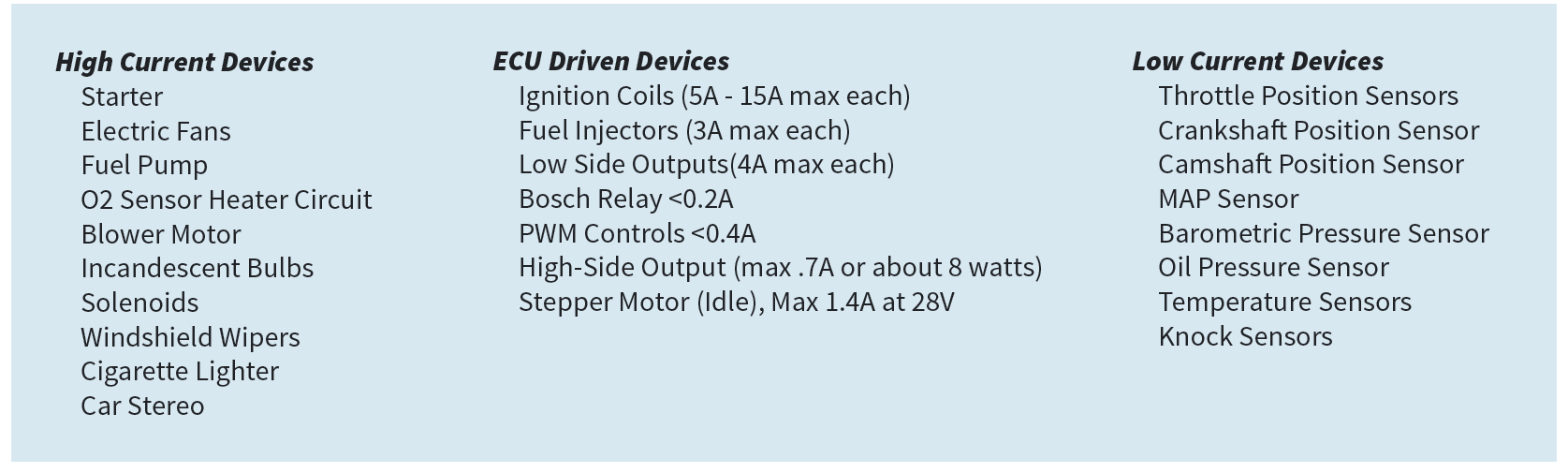
A low current knock sensor signals the ECU when vibrations from detonation or preignition occur. The ECU can then retard ignition timing when a spark knock is sensed.
Knock, Knock: Nissan and Non-Bosch Knock Sensors
Bosch, JECS, Denso and a number of other manufacturers all make doughnut-style knock sensors that look and fit the same. They all have two pins and the same connectors. Nissan and many Japanese OEMs use a JECS or DENSO sensor while some of the European applications use a Bosch sensor. While the Bosch sensor keeps both of the pins isolated from chassis ground, a JECS or DENSO (and many other replacement non-genuine Bosch knock sensors) actually ground one of the pins. This causes the sensor ground to be tied into the chassis ground. Once that happens, noise becomes excessive and then you are spending thousands of hours and dollars trying to write a code for an ECU to work around a bad, but easily avoidable condition.
Best Practices Electrical Circuits
- Use Battery (-) as ground for your DMM (not chassis)
- Use a DMM with high-impedance inputs
- Test Circuits While Connected and “On”
- Always back probe connections
- Install high-power devices as close to the battery as possible
Voltage offsets
1. Sensor description and math examples
From an electronics perspective, many common sensors operate as a resistor or a pair of resistors, and the resistance between the sensor’s pins changes depending on the pressure, temperature, or position of the object the sensor is measuring.
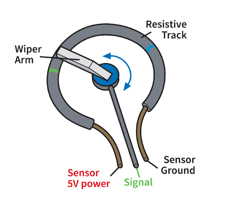
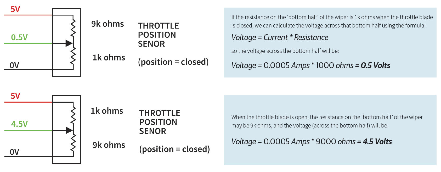
For instance, a TPS sensor is usually built using a track of resistive material with a wiper that moves when the throttle shaft rotates. The ECU provides Sensor 5V power and Sensor ground to the sensor, and measures the resulting voltage at the center pin, which will depend on the wiper position.
For example, let’s assume that the total track resistance is 10k ohms. The total current through the track will always be constant.
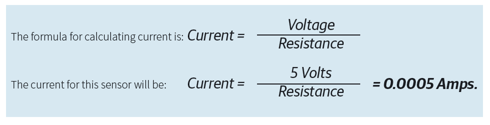
In this example, knowing the current is useful because it helps predict the voltage that will be measured by the ECU when the throttle is open or closed.
2. Shared wires
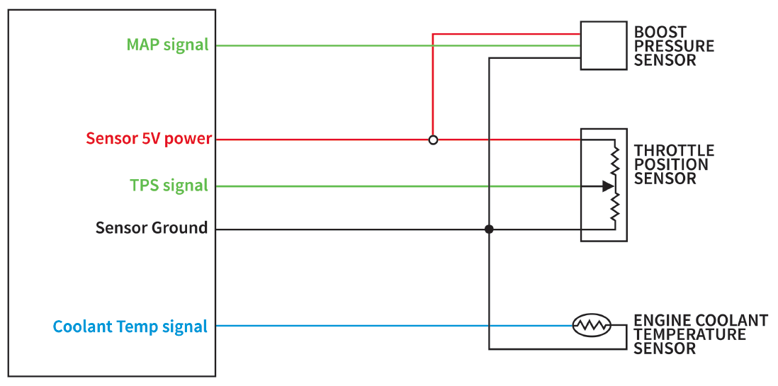
Multiple sensors need to be connected to common signals like ‘Sensor 5V power’ and ‘Sensor Ground.’ It’s typical for these common signals to travel on a single shared wire in part of the harness, then that shared wire branches out to each individual sensor somewhere in the harness.
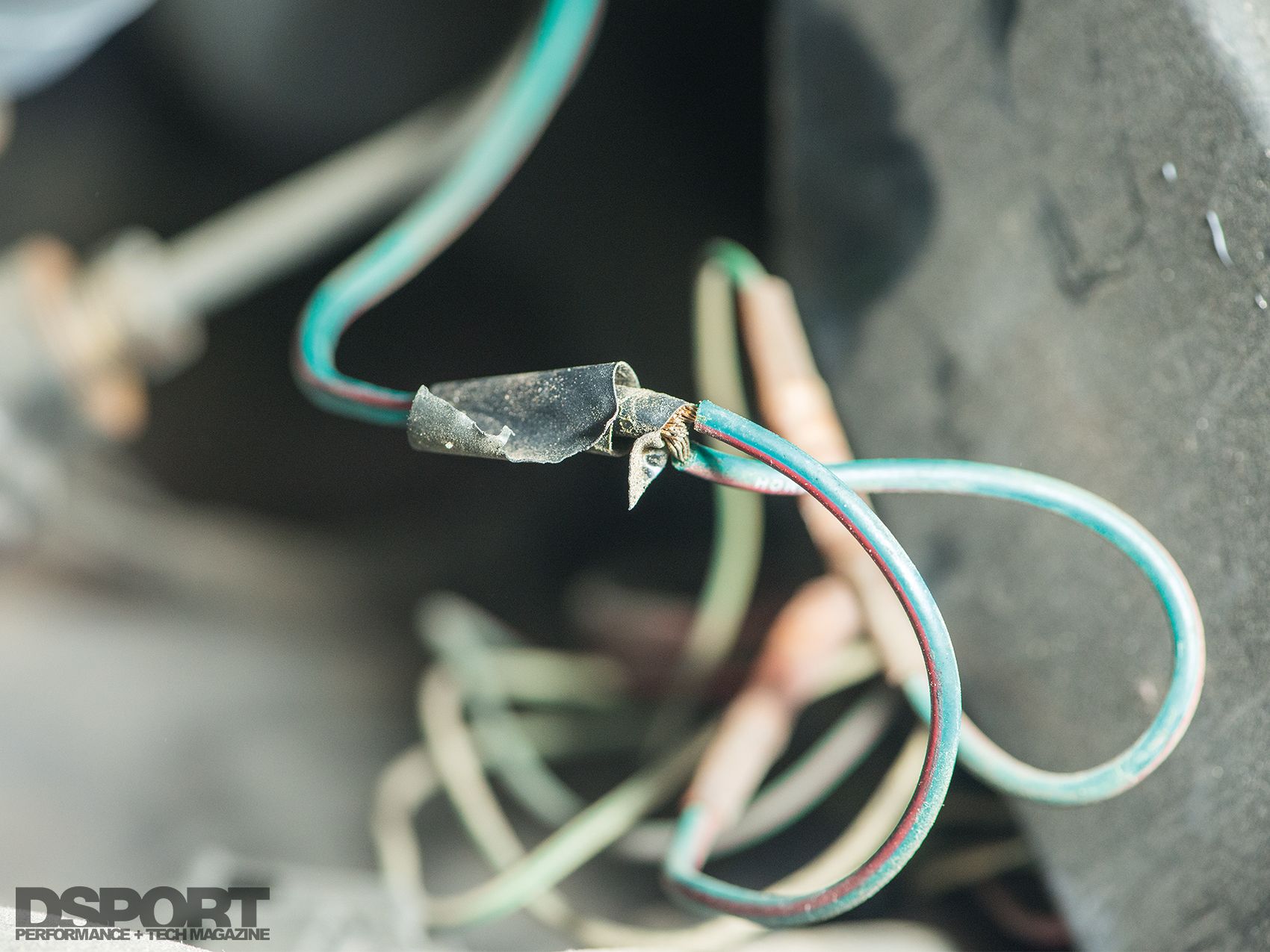
Voltage offsets can result in a few different ways; most of the ways are related to these shared wires. For demonstration purposes, a simple problem to describe is a poor wiring connection between the ECU and the sensor. A poor connection could be a wire that has most (but not all) of its strands broken, a terminal that is not making proper contact, or a splice that was soldered (which should always be avoided) or crimped improperly. From an electronics perspective, the poor connection can act like an additional resistor in the circuit.
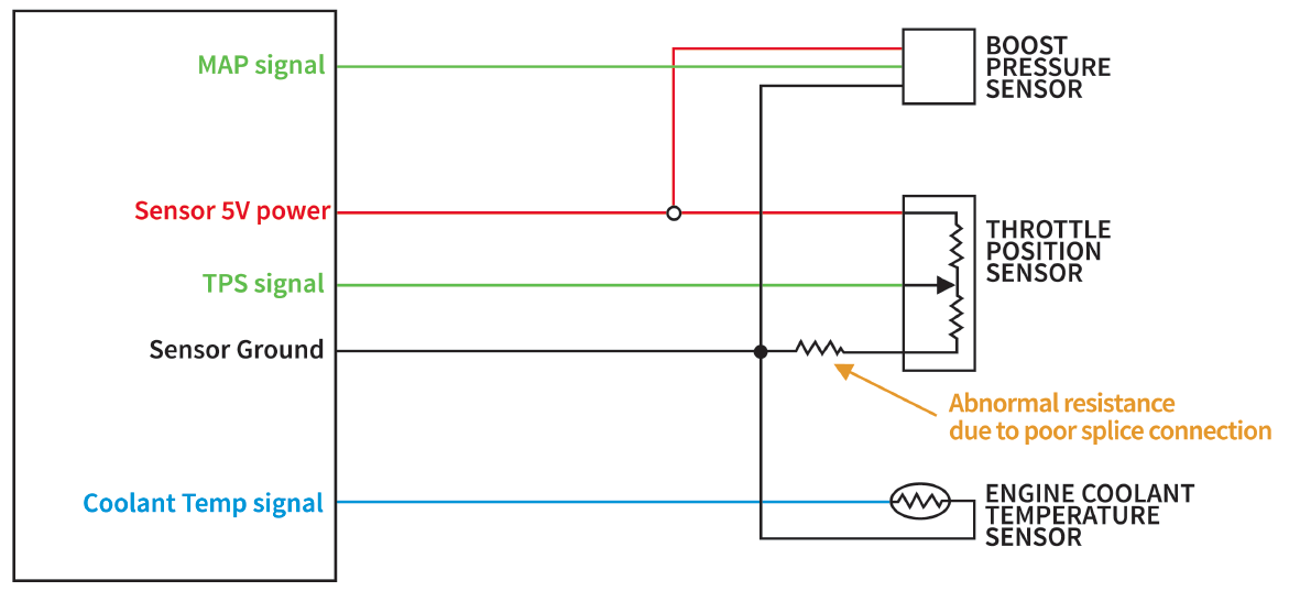
3. Added Resistance
Let’s assume there is an additional 3000 ohms of abnormal resistance due to the poor splice connection. Even though the sensor resistance has not changed, the effect of this additional resistance acts like the ‘bottom half’ of the wiper is 3000 ohms higher than usual. Repeating the original calculations, the total current will now be:

Using the new current value, and the additional 3000 ohms resistance, we can calculate the voltage the ECU will measure for the TPS signal:

This is significantly higher than the original value of 0.50V. Repeating the calculations for the fully open position predicts the TPS signal voltage will be and 4.61V rather than the original value of 4.50V.
In this example, if you measure voltage between the ECU’s sensor ground pin and the Throttle Position Sensor’s ground pin, you would find there is a 1.1V difference between the ECU’s sensor ground pin and the Throttle Position Sensor’s ground pin. This is often called a ‘ground offset,’ and it’s a situation we want to avoid. Note that the multimeter should be in ‘Volts DC’ mode, and the probes must measure the wires while everything is plugged in and operating.
4. ‘Normal’ vs ‘Abnormal’ ground offset values
If you measure closely, every wire has a small amount of resistance so it’s perfectly OK to have a very small ground offset. For instance, let’s repeat those calculations assuming that all the splices and connections are good, and there is 1 ohm of resistance on the shared sensor ground wire. Note that 1 ohms of wire resistance is higher than we would expect to see in most cases, for instance a 10-foot length of 22 gauge wire should measure approximately 0.1-0.2 ohms.

1 ohm of resistance barely affects the total current through our example sensor, calculations predict it will change from 0.00050000 amps to 0.00049995 amps; a difference so small it’s unlikely to be detected by most measuring equipment. The voltage measured at the sensor’s ground pin would be 0.0005 V, such a small difference that it would be difficult to even detect with most equipment. In other words, the ground offset is essentially zero, much too small to cause any problems.
These calculations assume that the Throttle Position Sensor is the only device drawing current through that shared sensor ground wire. If there are four other sensors each drawing an additional 0.0005 amps, the total current through the 1-ohms length of shared wire would be 0.002 amps, which means the voltage measured at the sensors’ ground pins will be (Voltage = 0.002 amps *1 ohm) = 0.002 Volts. A ground offset of 0.002 Volts is low enough it would not be noticed; the measurement error would be about 0.04% for most throttle position sensors, and about 0.2 kPa (0.04 psi) for a 5-bar MAP sensor.
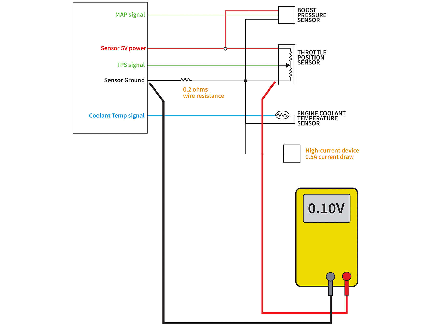
We may start to notice problems if there was an abnormally high amount of current being drawn through the shared length of sensor ground wire. For instance, if a boost gauge with an old-school incandescent light bulb was connected to the sensor ground wire it could draw an additional 0.5 amps of current. Assuming an abnormally high 1-ohms wire resistance, we would see an additional 0.5V ground offset between the ECU’s sensor ground pin and the sensors that are connected to that shared wire, which is pretty significant compared to normal sensor measurements.
Even assuming a normal 0.2-ohms wire resistance, an additional 0.5 amps drawn through a shared wire will cause an additional 0.10V ground offset. In terms of measured signals, an offset of 0.10V is approximately 2% throttle position, or 10 kPa (1.4 psi) for a 5-bar MAP sensor.
In addition to checking voltage, current, continuity and resistance some digital multimeters have the ability to test diodes, measure temperature, pulse widths and RPM.
5. Conclusion
To summarize, voltage offsets can occur when there is abnormally high current being drawn through shared sensor or supply wires, or abnormally high resistance between the ECU and the sensor due to harness or connector problems, or a combination of both. Only low-current sensors should be connected to the ECU’s sensor ground wire. High-current devices such as a relay control wires, switches that connect to ground, Ethanol content sensors, wideband gauge, solenoids, or indicator lamps should not be connected to the ECU’s sensor ground pin. For this reason, it’s a bad idea to connect the sensor ground wire to the engine block, intake manifold, or other parts that may indirectly provide a path for current to be drawn by the alternator, starter, or ignition coils.
